by Administrator
post 1
gddfg
The Water Distribution Uniformity (DU & CU)
The uniformity coefficient (CU), an important parameter in the design of irrigation systems, significantly affects the quality and return on investment in irrigation projects, and is a good indicator of water losses.
Steps for data collection
1. Placing the sprinklers in such a way that the distance between sprinklers in the column & rows is equal (for example here it is 10 metre). So 9 rectangular areas- each defined by 4 sprinklers at its 4 corners.
2. Place catch can in equal distance between the axes
• 1 metre or less on both axes for sprinklers (flow rate ≥ 200 l/h)
• ½ metre or less on both axes for micro-sprinklers (flow rate < 200 l/h)
Note: all gauges should be identical and should be positioned at the same elevation.
3. The effect of wind on distribution uniformity is unpredictable. For accurate measurement, the system should not be operated under windy conditions.
4. The amount of water collected in each gauge or can is measured and the results (in millimetres) are recorded as a table from highest to lowest.
There are 3 methods for calculating distribution uniformity:
• Christiansen coefficient of uniformity (%CU)- known to produce the most flattering results
• Distribution uniformity (%DU)- known to be more rigorous than %CU
• Scheduling coefficient (SC)- known to be the most rigorous method of all
Christiansen Coefficient of Uniformity (%CU)
% CU is the measure of uniformity expressed as the average rate (%) of deviation from the overall average application.
For open field sprinkler irrigation, %CU of:
• 92% or higher- Excellent uniformity
• 88% to 92%- Very good uniformity
• 86% to 88%- Good uniformity
• Lower than 86%- Acceptable for certain low-value crops only
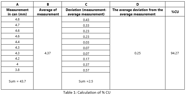
Sample calculation of %CU
For example, we are placing 10 cans between that sprinkler area, after one hour note the readings
1. The level of water in each can is noted as A
2. All the numbers in the A column are summed up and found the average value (B)
3. Noted down deviation from the average value (C). note: deviation is noted only in a positive number
4. Summing up all deviation value
5. The sum is divided by the number of gauges/cans placed in the field. This provides the average deviation from the average measurement. (D)
So, %CU= {1 – (Average deviation from average measurement / Average of measurement)} x 100
= {1 – (D/A) = 1 – (0.25/.37)} x 100 = 94.27%
So, %CU = 94.27% |
Distribution uniformity (%DU)
% DU is a measure of uniformity, with the dry 25% of the surveyed area as a percentage of the total average net application.
So, % DU= 93.3% |
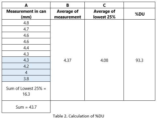
Advantage of the %DU method:
The %DU measurement takes into account the driest results. Therefore, it is better than% CU because it compares the area with the lowest water availability to the average application of the whole area.

Types of pump cavitation
Cavitation is the formation and subsequent collapse or implosion of vapour bubbles within the pump. It occurs because the absolute pressure on the liquid falls below the vapour pressure of the liquid. Ie, the pressure of the liquid falls below its vapour pressure, and the sudden collapsing of this vapour bubbles in a region of higher pressure. When the vapour bubbles collapse with enough frequency, we can hear a strange noise coming from the pump.
There are five recognized types of cavitation
<o:p></o:p>
· Vaporization cavitation
· Internal recirculation cavitation<o:p></o:p>
· Vane passing syndrome cavitation<o:p></o:p>
· Air aspiration cavitation<o:p></o:p>
· Turbulence cavitation<o:p></o:p>
Vaporization cavitation
Vaporization cavitation represents about 70 percent of all cavitation. At what temperature does water boil? Well, it depends on the pressure. If the temperature is high enough, the water will boil. If the pressure is too low, the water will boil. Under the right conditions, the liquid may boil or evaporate into the impeller's eye. When this happens, we say that the pump is experiencing vaporization cavitation.<o:p></o:p>
To prevent this type of cavitation, the NPSHa in the system must be higher than the NPSHr of the pump.<o:p></o:p>
A good suggestion to prevent vaporization cavitation is:<o:p></o:p>
NPSHa > NPSHr + 3 ft or more safety margin<o:p></o:p>
To prevent this type of cavitation damage:<o:p></o:p>
1. Lower the temperature of the liquid. <o:p></o:p>
2. Raise the liquid level on the suction side. <o:p></o:p>
3. Changing the pump.<o:p></o:p>
■ Reduce the speed of the pump. <o:p></o:p>
■ Increase the diameter in the impeller eye. <o:p></o:p>
■ Replace with two lower capacity pumps in parallel. <o:p></o:p>
■ Use a booster pump.<o:p></o:p>
Internal Recirculation
This cavitation is the result of a low flow condition, where the discharge flow of the pump is restricted. The liquid is forced to recirculate from high-pressure zones in the pump and to low-pressure zones across the impeller. This type of cavitation originates from two sources, first, the liquid is circulating inside the volute of the pump at the speed of the pump and rapidly overheats, second, the liquid is forced to pass tight tolerances at very high speed.<o:p></o:p>
To prevent this type of cavitation damage:<o:p></o:p>
· Check the downstream filter of any debris or accumulation.<o:p></o:p>
· Check the discharge valve and make sure it is open and not closed.<o:p></o:p>
· Make sure the check valve is installed properly. A common mistake during installation is to attach this valve to the rear.<o:p></o:p>
Vane Passing Syndrome
This type of cavitation can exist when the blade tips at the outside diameter of the impeller are passing too close to the cutwater of the pump casing. Make sure the gap between your impeller and its housing (cutwater clearance) is 4% of your impeller diameter. Fig.2 illustrates cutwater clearance.
fig.2: Cutwater clearance
Air Aspiration
This can be difficult to prevent. Even the smallest amount of air drawn into the system can cause the cavitation over time. The best approach is to make sure all joints and connections are properly sealed.<o:p></o:p>
To prevent this type of cavitation, you need to seal all points of entrance and escape<o:p></o:p>
Turbulence Cavitation
This type of cavitation is due to turbulence caused by inadequate piping, Sharp elbows, formation of vortexes in the suction flow<o:p></o:p>
Preventive steps<o:p></o:p>
· Increase the pump suction line size to reduce turbulence<o:p></o:p>
· Make sure you do not exceed the performance guidelines of your pump manufacturer.<o:p></o:p>
Electro Fusion (EF) Welding of PE Pipes & Fittings
EF Welding Machine
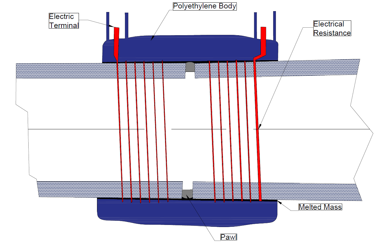
Fig. 1. EFW Setup
Types of EF Welding Machines
Decoding the EF Barcode
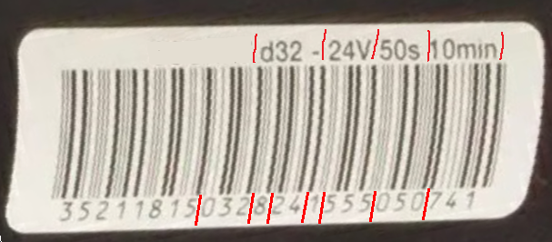
- The first 8 digits represents the manufacturer's code.
- The digits 9 to 11 represents the dimension of the item in mm.
- The digits 13 & 14 indicates the EFW voltage in volts.
- The digits 16 to 18 represents the resistance in ohms.
- The digits 19 to 21 represents the fusion time needed for joining the fitting in seconds.
- The dimension (mm), voltage (V), fusion time (s), and cooling time (min) is indicated at the top of the barcode.
BSPT Thread Standards
British Standard Pipe Taper aka BSPT threads are governed by ISO 7 standards. The male threads are usually designated as "R" while the female threads are usually designated as "Rc". The fig.1 below illustrates the nomenclature related to the thread where the thread angle is 55 degrees.
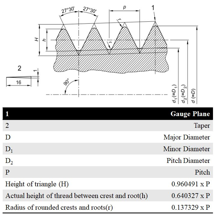
Fig. 1: The BSPT Thread Nomenclature
BSPT Male Thread Standards (R)
Size | D (mm) | D1 (mm) | D2 (mm) | h (mm) | P (mm) | TPI | Min. Gauge |
1/16" | 7.723 | 6.561 | 7.142 | 0.581 | 0.907 | 28 | 5.6 |
1/8" | 9.728 | 8.566 | 9.147 | 0.581 | 0.907 | 28 | 5.6 |
1/4" | 13.157 | 11.445 | 12.301 | 0.856 | 1.337 | 19 | 8.4 |
3/8" | 16.662 | 14.950 | 15.806 | 0.856 | 1.337 | 19 | 8.8 |
1/2" | 20.955 | 18.631 | 19.793 | 1.162 | 1.814 | 14 | 11.4 |
3/4" | 26.441 | 24.117 | 25.279 | 1.162 | 1.814 | 14 | 12.7 |
1" | 33.249 | 30.291 | 31.770 | 1.479 | 2.309 | 11 | 14.5 |
1 1/4" | 41.910 | 38.952 | 40.431 | 1.479 | 2.309 | 11 | 16.8 |
1 1/2" | 47.803 | 44.845 | 46.324 | 1.479 | 2.309 | 11 | 16.8 |
2" | 59.614 | 56.656 | 58.135 | 1.479 | 2.309 | 11 | 21.1 |
2 1/2" | 75.184 | 72.226 | 73.705 | 1.479 | 2.309 | 11 | 23.2 |
3" | 87.884 | 84.926 | 86.405 | 1.479 | 2.309 | 11 | 26.3 |
4" | 113.03 | 110.07 | 111.55 | 1.479 | 2.309 | 11 | 32.3 |
5" | 138.43 | 135.47 | 136.95 | 1.479 | 2.309 | 11 | 36.6 |
6" | 163.83 | 160.87 | 162.35 | 1.479 | 2.309 | 11 | 36.6 |
BSPT Thread Standards (Rc)
Size | D2 or Hole Size (mm) |
1/16" | 6.470 |
1/8" | 8.495 |
1/4" | 11.340 |
3/8" | 14.846 |
1/2" | 18.489 |
3/4" | 23.975 |
1" | 30.110 |
1 1/4" | 38.802 |
1 1/2" | 44.665 |
2" | 56.476 |
2 1/2" | 72.010 |
3" | 84.710 |
Thread Compatibility
Thread Profile | Matching Profile | Seal Type |
BSPT Female Thread (Rc) | BSPT Male Thread (R) | Tape or Pipe dope |